This post is a summary of a Deskthority thread that I created in 2018. I’ve tried my best to piece the details together.
Introduction
At some point I purchased a very dirty NEC PC-8810 keyboard with blue Alps that was exceptionally dusty. My original plan was just to clean it up and sell it, but I soon became enthralled with the idea of converting the keyboard to USB.
Clean Up
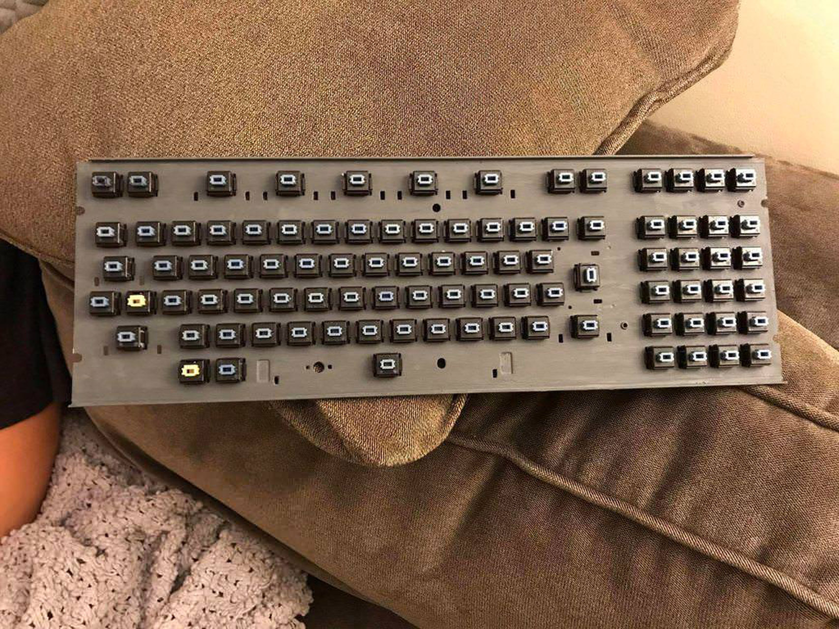
As I mentioned, the board was super dusty under the caps, so my first job was to give it a good cleaning.
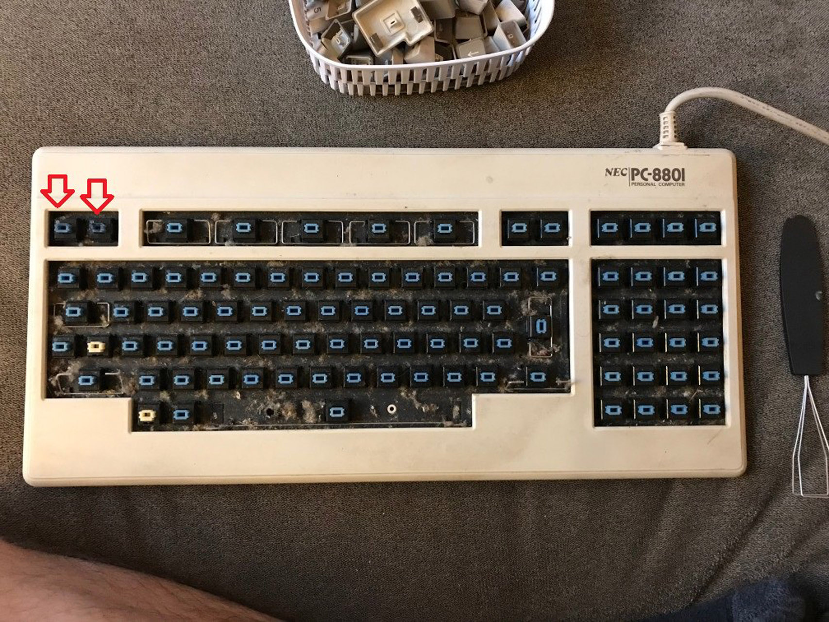
The two arrows in the photo above turned out to be SKCM heavy blues, which are around 200g force to press. I desoldered all of the switches and broke down the board into components.
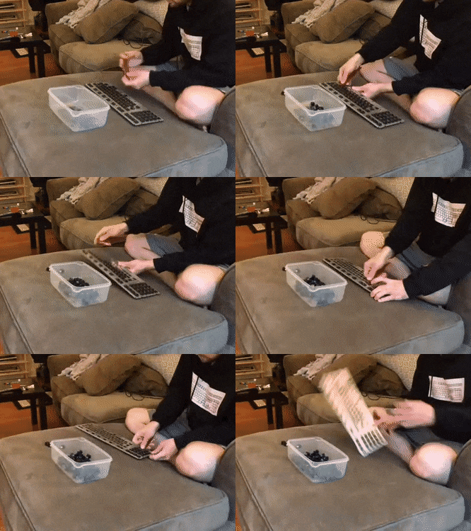
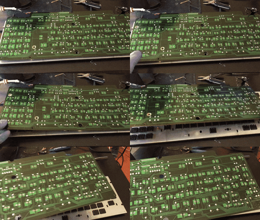
Then I stripped all of the rust off the plate and painted it. Cleaned all of the switches and reinstalled them.
Analysis
I bought a pack of these connector plugs, but they unfortunately the pins were not very accessible. So I ended up making a really messy but functional cable connector with a bunch of wire head-shrink tubes.
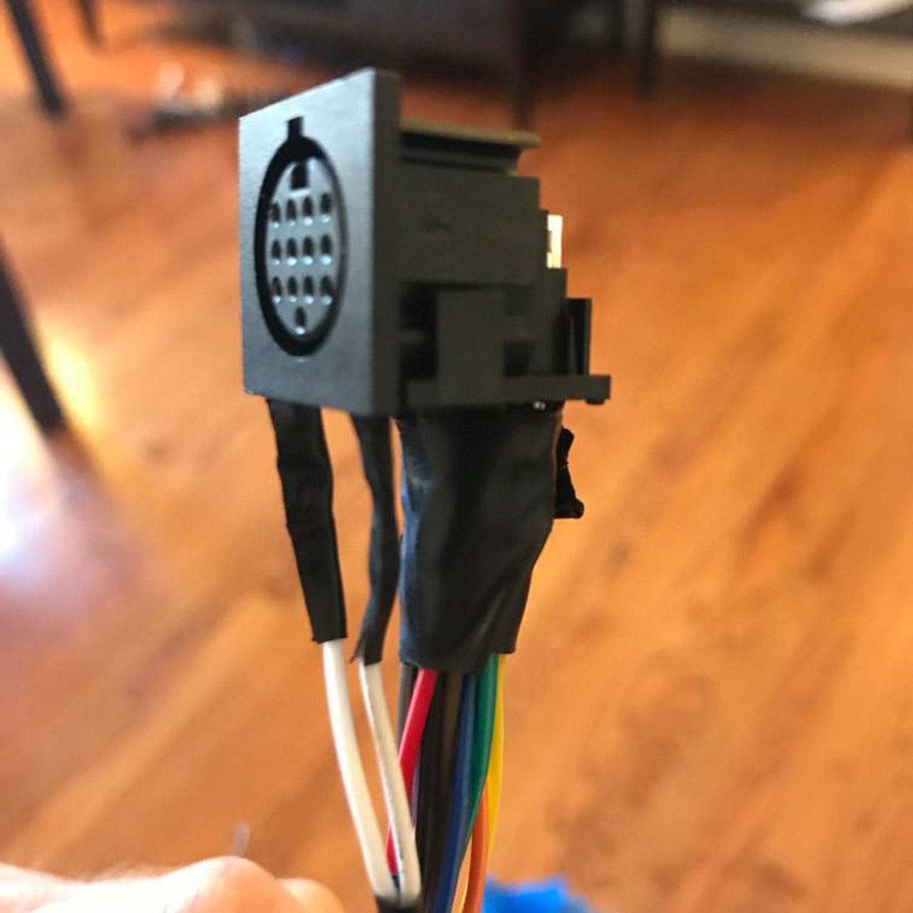
I used a multimeter in continuity mode to do some basic tracing of the pins for the cable.
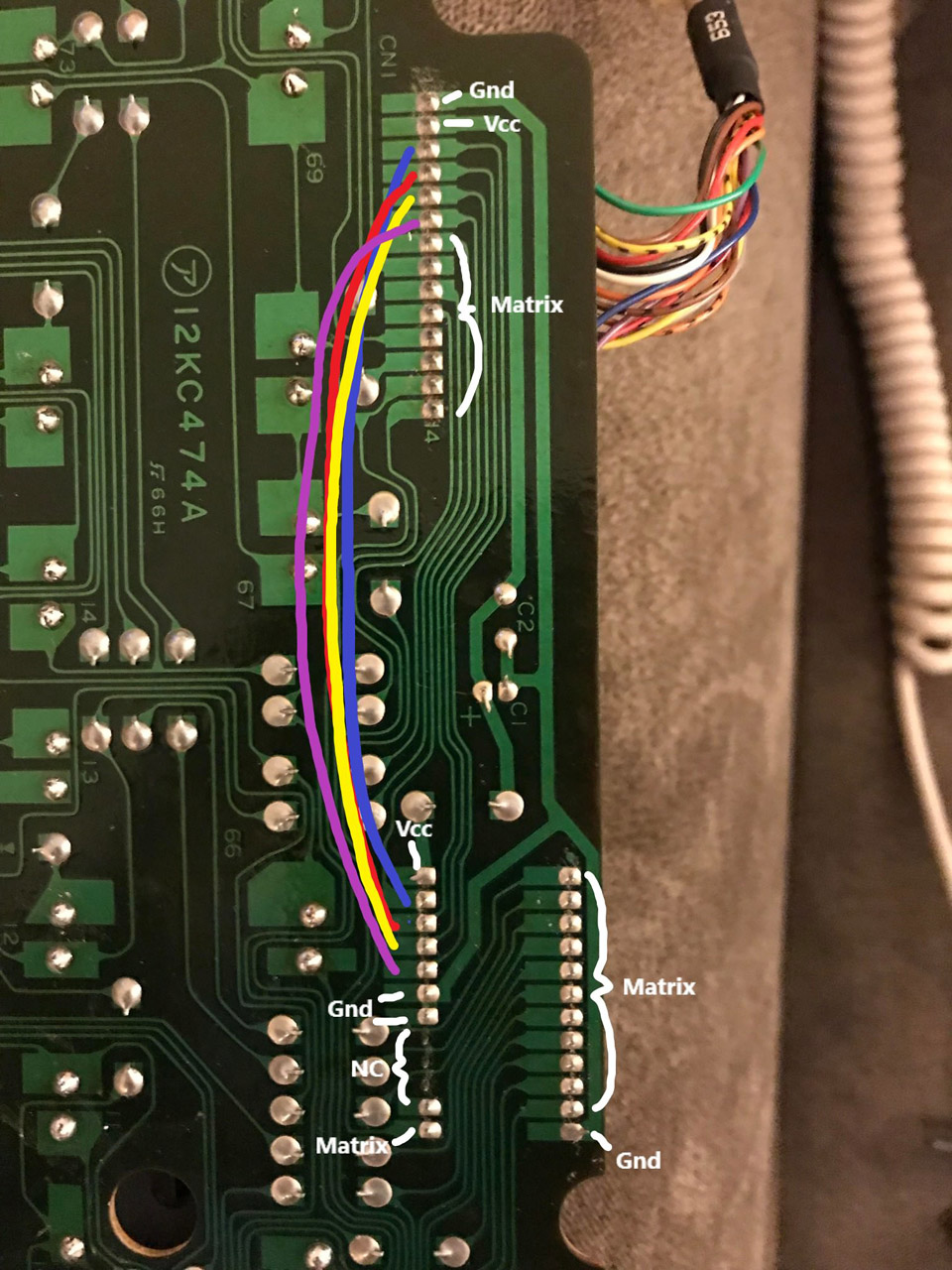
I found a blog post by Leaded Solder who had the actual computer itself and was trying to reverse engineer the keyboard. This was a super helpful find.
This explanation of how the keyboard works definitely pointed me in the right direction.
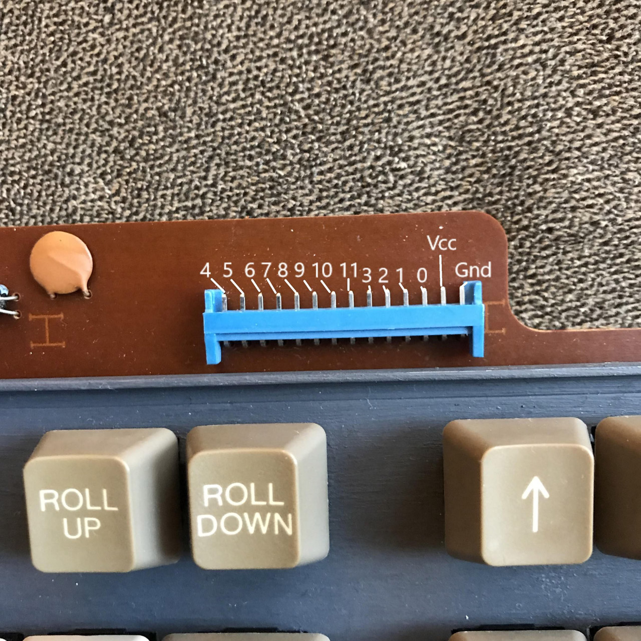
What this means in practice is that the PC88 itself does the key reading. The keyboard connector has 13 pins (14 if you count the ground sleeve), and in order to read a key, the computer triggers four of those pins. A multiplexer on the keyboard uses those four lines to activate the appropriate row on the keyboard matrix, and eight lines are triggered in response to tell the computer which keys on that row are pressed.
I confirmed with a quick and dirty Arduino sketch that this is most likely how the keyboard reading works.
My sketch pulls one of the signal pins low then reads each of the remaining 8 pins. If you press a key on the keyboard that’s in the row corresponding to the signal pin that was pulled low, the sketch will output the matching column number.
I ran my sketch for each key and compared against the memory map table from leadedsolder and everything matched up with just a couple of exceptions where a keypress didn’t generate any output.
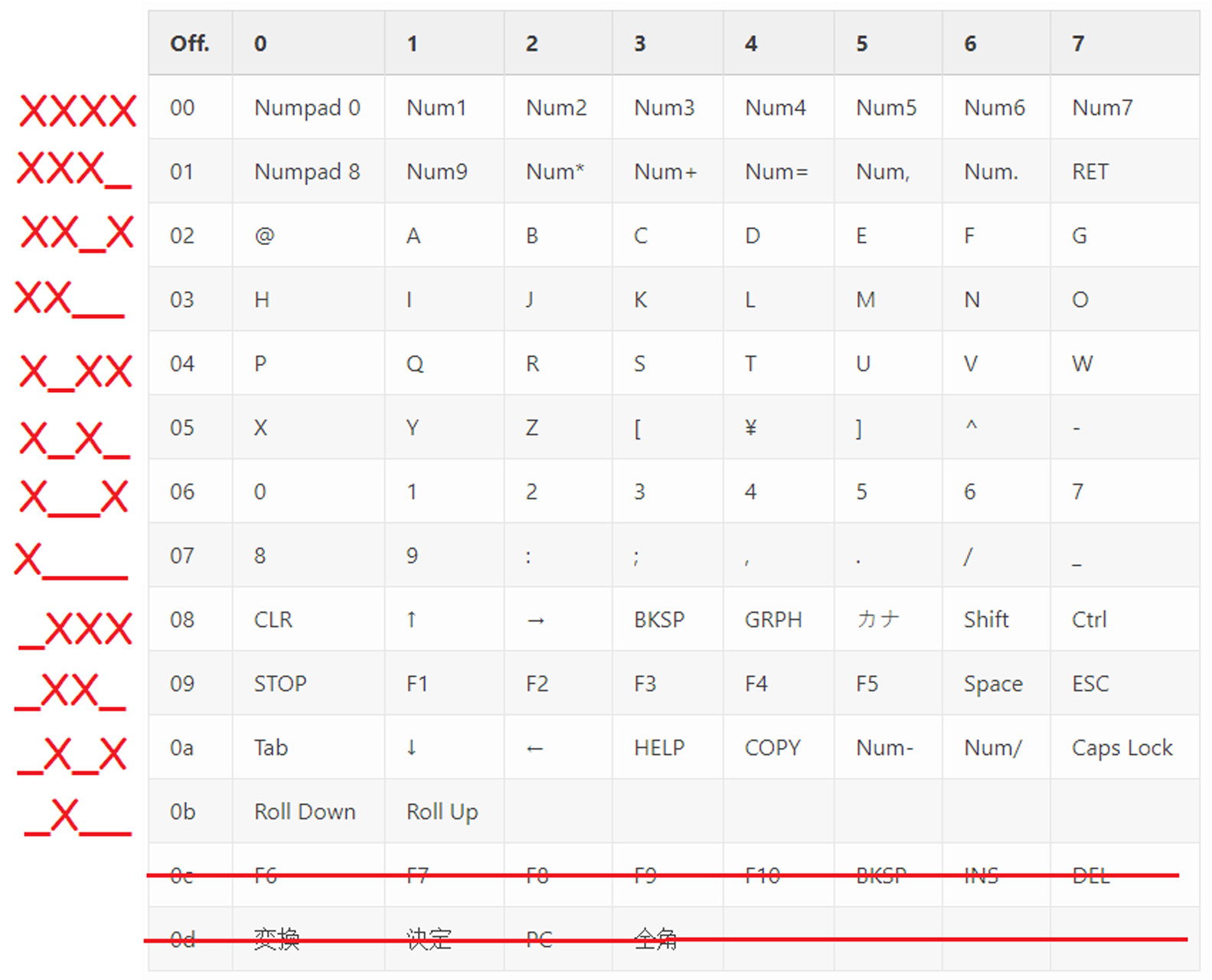
I eventually was able to revise my Arduino sketch into a working prototype converter.
Converter
Pinout
I used a Teensy 2.0 which has this pinout:
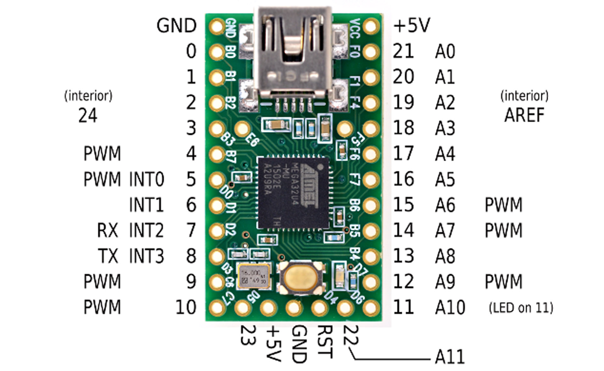
The corresponding pins on the keyboard connector are:
Code
Here is the code for the converter. I’m using the arduino keyboard library so if you’d like to switch around the keymap, you can use this page to find all the keycodes. To compile the sketch in the arduino IDE, make sure you’ve set the USB type to keyboard by going to: Tools > Usb Type > Keyboard + Mouse + Joystick.
A big thank you again to the author of leadedsolder.com whose posts were key in getting this working.
|
|
